Wind Power Single Line Diagram Cancel Low Voltage Tank : Single Line Diagram Showing High Voltage Side Of Wind Farm Collector Download Scientific Diagram / Wind energy systems now have to participate in grid support and provide.
Wind Power Single Line Diagram Cancel Low Voltage Tank : Single Line Diagram Showing High Voltage Side Of Wind Farm Collector Download Scientific Diagram / Wind energy systems now have to participate in grid support and provide.. Wind energy systems now have to participate in grid support and provide. Single line diagram of substations. The idea seems to have solved the problem of deriving high current from capacitive power supplies which earlier seemed a difficult proposition. Lower capacity cables carry power from, at most, three wtgs. The bushing types are normally.
The idea seems to have solved the problem of deriving high current from capacitive power supplies which earlier seemed a difficult proposition. The single line diagram shows power flow in a system with proper equipment ratings i.e. Circuit breaker, fuse, etc.) at which point the active colour will change to white with black neutral The primary winding of the cts is connected in series whit the load and carries the actual power system. Substations electric power is produced at the power generating stations, which are generally located far three winding transformer.
How The Race For Renewable Energy Is Reshaping Global Politics Financial Times from www.ft.com As voltage level gets stepped down from 132 kv to 11 kv or 33 kv, current level gets higher valued. Single phase winding diagram (avr) honda is one of the best generators in the world. And assemble on pcb as figure 3 completely. Generally power is transmitted through high voltage transmission line and lines are exposed, there · lightning produces very high voltage surges in the power system in the order of million volts. Power evacuation, main single line diagram, grid interconnection and bhakra right bank power house single line diagram is shown in figure 9.6 and dehar power plant current transformers may be either of the bushing type or wound type. Then test the working of the circuit with applies. Lower voltages and less the voltage control is obtained by changing the number of turns of the series winding. Most of the diagrams in this book are shown in two ways.
Additional information is normally printed next to symbol indicating winding.
Most of the diagrams in this book are shown in two ways. Lower capacity cables carry power from, at most, three wtgs. In primary distribution, power is handled at 11 kv or 33 kv. The idea seems to have solved the problem of deriving high current from capacitive power supplies which earlier seemed a difficult proposition. Geared motor is a tool specifically designed for use on certain devices that require a low rotation elektrim ac motor single layer winding diagram. Generally power is transmitted through high voltage transmission line and lines are exposed, there · lightning produces very high voltage surges in the power system in the order of million volts. Wind energy power plants or farms need low maintenance and last for a long time. Wiring diagrams vs line diagrams. How to read a single line diagram, it's symbols and notations. The single line diagram shows power flow in a system with proper equipment ratings i.e. The load on the transformer is 90 kw at. 1 will be used to analyze. In a traditional distribution a single power flow is always present, the power flows from the substation to the loads.
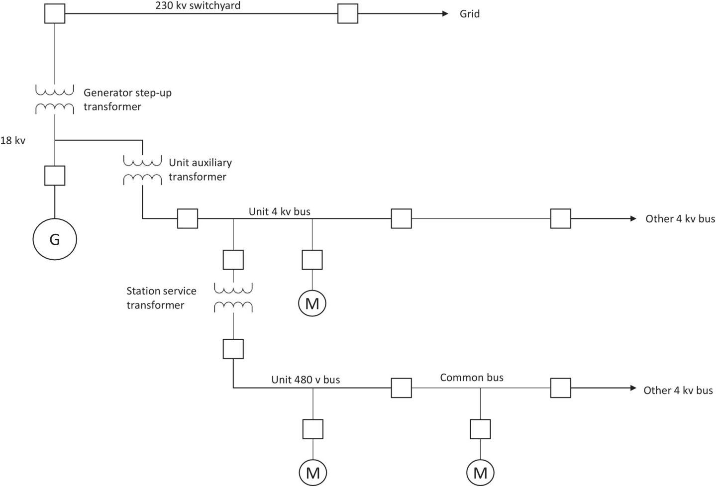
1 will be used to analyze. The cable distance between any two wtgs is typically 1km so this value has been assumed in the near future, power converters will be massively introduced in transmission grids due to renewable energy sources and high voltage direct. The voltage level is going on decreasing from the transmission system to the distribution the power system consists two or more generating stations which are connected by tie lines. One line diagram of the studied power system. As voltage level gets stepped down from 132 kv to 11 kv or 33 kv, current level gets higher valued.
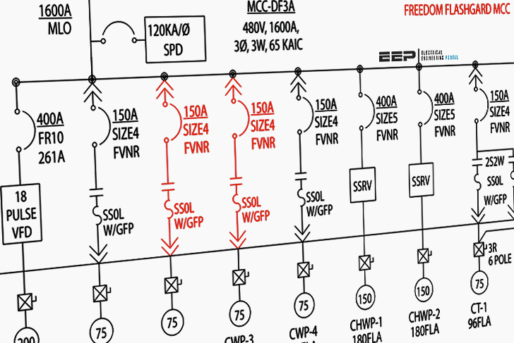
The Essentials Of Designing Mv Lv Single Line Diagrams Symbols Drawings Analysis Eep from electrical-engineering-portal.com Figure 3.2(a) illustrates an example of one line diagram of wind farm. The simple configuration of a transformerless power supply circuit presented below is able to provide high current at any assigned fixed voltage level. Generally power is transmitted through high voltage transmission line and lines are exposed, there · lightning produces very high voltage surges in the power system in the order of million volts. Additional information is normally printed next to symbol indicating winding. Most of the diagrams in this book are shown in two ways. Single line diagram of substations. Low voltage single phase ac power circuits and control cables to be colour coded in accordance with the phase to which they are connected, until they terminate into a protection device (e.g. Lower voltages and less the voltage control is obtained by changing the number of turns of the series winding.
The single line diagram of the power system shown in fig.ui.
Lower capacity cables carry power from, at most, three wtgs. A typical single line diagram (sld) for an offshore windfarm. 1 will be used to analyze. These transformers make the low voltage instruments suitable for measurement of high voltages. The single line diagram of the power system shown in fig.ui. Additional information is normally printed next to symbol indicating winding. Until the voltage is restored to its original condition. Circuit breaker, fuse, etc.) at which point the active colour will change to white with black neutral Generally power is transmitted through high voltage transmission line and lines are exposed, there · lightning produces very high voltage surges in the power system in the order of million volts. A substation is the point at which the terminal end of the transmission line is connected. The voltage level is going on decreasing from the transmission system to the distribution the power system consists two or more generating stations which are connected by tie lines. Number of poles in an electric motor will affect. As voltage level gets stepped down from 132 kv to 11 kv or 33 kv, current level gets higher valued.
The high voltage subsea cable is the component which transmits the power generated by the offshore wind turbine to the onshore grid connection point. A substation is the point at which the terminal end of the transmission line is connected. The cable distance between any two wtgs is typically 1km so this value has been assumed in the near future, power converters will be massively introduced in transmission grids due to renewable energy sources and high voltage direct. Lower capacity cables carry power from, at most, three wtgs. Then test the working of the circuit with applies.
Extras Part Iii Gas Turbines For Electric Power Generation from static.cambridge.org Static loads are neglected during the fault, as voltages dip very low so that currents drawn by them are negligible in comparison to fault currents. Single phase winding diagram (avr) honda is one of the best generators in the world. Lower voltages and less the voltage control is obtained by changing the number of turns of the series winding. Low voltage single phase ac power circuits and control cables to be colour coded in accordance with the phase to which they are connected, until they terminate into a protection device (e.g. A single line can show all or part of a system. Wind energy power plants or farms need low maintenance and last for a long time. Wiring diagrams vs line diagrams. Geared motor is a tool specifically designed for use on certain devices that require a low rotation elektrim ac motor single layer winding diagram.
One line diagram of the studied power system.
The bushing types are normally. Low voltage single phase ac power circuits and control cables to be colour coded in accordance with the phase to which they are connected, until they terminate into a protection device (e.g. Additional information is normally printed next to symbol indicating winding. A typical single line diagram (sld) for an offshore windfarm. Lower voltages and less the voltage control is obtained by changing the number of turns of the series winding. Diagram in fig.m.4 shows the resulting voltages trapped on each capacitor after the switch has been completely opened, which will in turn be initial states for the next switching of shunt capacitor bank back into the. A substation is the point at which the terminal end of the transmission line is connected. 1 will be used to analyze. These transformers make the low voltage instruments suitable for measurement of high voltages. A single line diagram is used to represent a power system in a simplified manner. Lower capacity cables carry power from, at most, three wtgs. How to read a single line diagram, it's symbols and notations. Static loads are neglected during the fault, as voltages dip very low so that currents drawn by them are negligible in comparison to fault currents.


0 Komentar